Related Plugins and Tags

QGIS Planet

Tracking geoprocessing workflows with QGIS & DVC

Today’s post is a geeky deep dive into how to leverage DVC (not just) data version control to track QGIS geoprocessing workflows.

“Why is this great?” you may ask.

DVC tracks data, parameters, and code. If anything changes, we simply rerun the process and DVC will figure out which stages need to be recomputed and which can be skipped by re-using cached results.

This can lead to huge time savings compared to re-running the whole model

You can find the source code used in this post on my repo https://github.com/anitagraser/QGIS-resources/tree/dvc

I’m using DVC with the DVC plugin for VSCode but DVC can be used completely from the command line, if you prefer this appraoch.

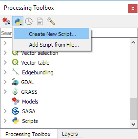
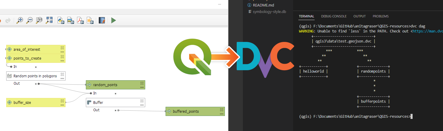
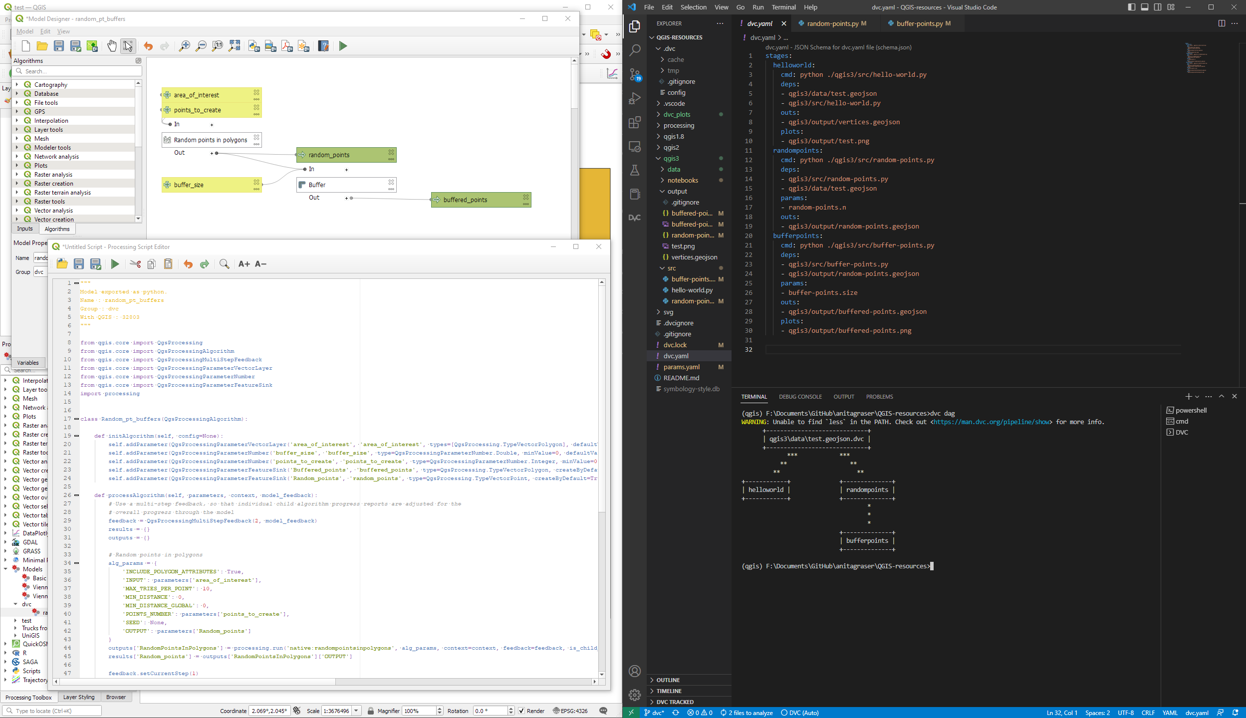
Basically, what follows is a proof of concept: converting a QGIS Processing model to a DVC workflow. In the following screenshot, you can see the main stages

  1. The QGIS model in the upper left corner
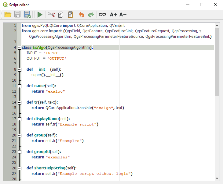
  2. The Python script exported from the QGIS model builder in the lower left corner
  3. The DVC stages in my dvc.yaml file in the upper right corner (And please ignore the hello world stage. It’s a left over from my first experiment)
  4. The DVC DAG visualizing the sequence of stages. Looks similar to the QGIS model, doesn’t it ;-)

Besides the stage definitions in dvc.yaml, there’s a parameters file:

random-points:
  n: 10
buffer-points:
  size: 0.5

And, of course, the two stages, each as it’s own Python script.

First, random-points.py which reads the random-points.n parameter to create the desired number of points within the polygon defined in qgis3/data/test.geojson:

import dvc.api

from qgis.core import QgsVectorLayer
from processing.core.Processing import Processing
import processing

Processing.initialize()

params = dvc.api.params_show()
pts_n = params['random-points']['n']

input_vector = QgsVectorLayer("qgis3/data/test.geojson")
output_filename = "qgis3/output/random-points.geojson"

alg_params = {
    'INCLUDE_POLYGON_ATTRIBUTES': True,
    'INPUT': input_vector,
    'MAX_TRIES_PER_POINT': 10,
    'MIN_DISTANCE': 0,
    'MIN_DISTANCE_GLOBAL': 0,
    'POINTS_NUMBER': pts_n,
    'SEED': None,
    'OUTPUT': output_filename
}
processing.run('native:randompointsinpolygons', alg_params)

And second, buffer-points.py which reads the buffer-points.size parameter to buffer the previously generated points:

import dvc.api
import geopandas as gpd
import matplotlib.pyplot as plt

from qgis.core import QgsVectorLayer
from processing.core.Processing import Processing
import processing

Processing.initialize()

params = dvc.api.params_show()
buffer_size = params['buffer-points']['size']

input_vector = QgsVectorLayer("qgis3/output/random-points.geojson")
output_filename = "qgis3/output/buffered-points.geojson"

alg_params = {
    'DISSOLVE': False,
    'DISTANCE': buffer_size,
    'END_CAP_STYLE': 0,  # Round
    'INPUT': input_vector,
    'JOIN_STYLE': 0,  # Round
    'MITER_LIMIT': 2,
    'SEGMENTS': 5,
    'OUTPUT': output_filename
}
processing.run('native:buffer', alg_params)

gdf = gpd.read_file(output_filename)
gdf.plot()

plt.savefig('qgis3/output/buffered-points.png')

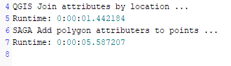
With these things in place, we can use dvc to run the workflow, either from within VSCode or from the command line. Here, you can see the workflow (and how dvc skips stages and fetches results from cache) in action:

If you try it out yourself, let me know what you think.

Easy Processing scripts comeback in QGIS 3.6

When QGIS 3.0 was release, I published a Processing script template for QGIS3. While the script template is nicely pythonic, it’s also pretty long and daunting for non-programmers. This fact didn’t go unnoticed and Nathan Woodrow in particular started to work on a QGIS enhancement proposal to improve the situation and make writing Processing scripts easier, while – at the same time – keeping in line with common Python styles.

While the previous template had 57 lines of code, the new template only has 26 lines – 50% less code, same functionality! (Actually, this template provides more functionality since it also tracks progress and ensures that the algorithm can be cancelled.)

from qgis.processing import alg
from qgis.core import QgsFeature, QgsFeatureSink

@alg(name="ex_new", label=alg.tr("Example script (new style)"), group="examplescripts", group_label=alg.tr("Example Scripts"))
@alg.input(type=alg.SOURCE, name="INPUT", label="Input layer")
@alg.input(type=alg.SINK, name="OUTPUT", label="Output layer")
def testalg(instance, parameters, context, feedback, inputs):
    """
    Description goes here. (Don't delete this! Removing this comment will cause errors.)
    """
    source = instance.parameterAsSource(parameters, "INPUT", context)

    (sink, dest_id) = instance.parameterAsSink(
        parameters, "OUTPUT", context,
        source.fields(), source.wkbType(), source.sourceCrs())

    total = 100.0 / source.featureCount() if source.featureCount() else 0
    features = source.getFeatures()
    for current, feature in enumerate(features):
        if feedback.isCanceled():
            break
        out_feature = QgsFeature(feature)
        sink.addFeature(out_feature, QgsFeatureSink.FastInsert)
        feedback.setProgress(int(current * total))

    return {"OUTPUT": dest_id}

The key improvement are the new decorators that turn an ordinary function (such as testalg in the template) into a Processing algorithm. Decorators start with @ and are written above a function definition. The @alg decorator declares that the following function is a Processing algorithm, defines its name and assigns it to an algorithm group. The @alg.input decorator creates an input parameter for the algorithm. Similarly, there is a @alg.output decorator for output parameters.

For a longer example script, check out the original QGIS enhancement proposal thread!

For now, this new way of writing Processing scripts is only supported by QGIS 3.6 but there are plans to back-port this improvement to 3.4 once it is more mature. So give it a try and report back!

Movement data in GIS #17: spatial analysis of GeoPandas trajectories

In Movement data in GIS #16, I presented a new way to deal with trajectory data using GeoPandas and how to load the trajectory GeoDataframes as a QGIS layer. Following up on this initial experiment, I’ve now implemented a first version of an algorithm that performs a spatial analysis on my GeoPandas trajectories.

The first spatial analysis algorithm I’ve implemented is Clip trajectories by extent. Implementing this algorithm revealed a couple of pitfalls:

  • To achieve correct results, we need to compute spatial intersections between linear trajectory segments and the extent. Therefore, we need to convert our point GeoDataframe to a line GeoDataframe.
  • Based on the spatial intersection, we need to take care of computing the corresponding timestamps of the events when trajectories enter or leave the extent.
  • A trajectory can intersect the extent multiple times. Therefore, we cannot simply use the global minimum and maximum timestamp of intersecting segments.
  • GeoPandas provides spatial intersection functionality but if the trajectory contains consecutive rows without location change, these will result in zero length lines and those cause an empty intersection result.

So far, the clip result only contains the trajectory id plus a suffix indicating the sequence of the intersection segments for a specific trajectory (because one trajectory can intersect the extent multiple times). The following screenshot shows one highlighted trajectory that intersects the extent three times and the resulting clipped trajectories:

This algorithm together with the basic trajectory from points algorithm is now available in a Processing algorithm provider plugin called Processing Trajectory.

Note: This plugin depends on GeoPandas.

Note for Windows users: GeoPandas is not a standard package that is available in OSGeo4W, so you’ll have to install it manually. (For the necessary steps, see this answer on gis.stackexchange.com)

The implemented tests show how to use the Trajectory class independently of QGIS. So far, I’m only testing the spatial properties though:

def test_two_intersections_with_same_polygon(self):
    polygon = Polygon([(5,-5),(7,-5),(7,12),(5,12),(5,-5)])
    data = [{'id':1, 'geometry':Point(0,0), 't':datetime(2018,1,1,12,0,0)},
        {'id':1, 'geometry':Point(6,0), 't':datetime(2018,1,1,12,10,0)},
        {'id':1, 'geometry':Point(10,0), 't':datetime(2018,1,1,12,15,0)},
        {'id':1, 'geometry':Point(10,10), 't':datetime(2018,1,1,12,30,0)},
        {'id':1, 'geometry':Point(0,10), 't':datetime(2018,1,1,13,0,0)}]
    df = pd.DataFrame(data).set_index('t')
    geo_df = GeoDataFrame(df, crs={'init': '31256'})
    traj = Trajectory(1, geo_df)
    intersections = traj.intersection(polygon)
    result = []
    for x in intersections:
        result.append(x.to_linestring())
    expected_result = [LineString([(5,0),(6,0),(7,0)]), LineString([(7,10),(5,10)])]
    self.assertEqual(result, expected_result) 

One issue with implementing the algorithms as QGIS Processing tools in this way is that the tools are independent of one another. That means that each tool has to repeat the expensive step of creating the trajectory objects in memory. I’m not sure this can be solved.

Optional parameters in QGIS Processing scripts & models

Remember the good old times when all parameters in Processing were mandatory?

Inputs and outputs are fixed, and optional parameters or outputs are not supported. [Graser & Olaya, 2015]

Since QGIS 2.14, this is no longer the case. Scripts, as well as models, can now have optional parameters. Here is how for QGIS 3:

When defining a Processing script parameter, the parameter’s constructor takes a boolean flag indicating whether the parameter should be optional. It’s false by default:

class qgis.core.QgsProcessingParameterNumber(
   name: str, description: str = '', 
   type: QgsProcessingParameterNumber.Type = QgsProcessingParameterNumber.Integer, 
   defaultValue: Any = None, 
   optional: bool = False,
   minValue: float = -DBL_MAX+1, maxValue: float = DBL_MAX)

(Source: http://python.qgis.org/api/core/Processing/QgsProcessingParameterNumber.html)

One standard tool that uses optional parameters is Add autoincremental field:

From Python, this algorithm can be called with or without the optional parameters:

When building a model, an optional input can be assigned to the optional parameter. To create an optional input, make sure to deactivate the mandatory checkbox at the bottom of the input parameter definition:

Then this optional input can be used in an algorithm. For example, here the numerical input optional_value is passed to the Start values at parameter:

You can get access to all available inputs by clicking the … button next to the Start values at field. In this example, I have access to values of the input layer as well as  the optional value:

Once this is set up, this is how it looks when the model is run:

You can see that the optional value is indeed Not set.

References

Graser, A., & Olaya, V. (2015). Processing: A Python Framework for the Seamless Integration of Geoprocessing Tools in QGIS. ISPRS Int. J. Geo-Inf. 2015, 4, 2219-2245. doi:10.3390/ijgi4042219.

Processing script template for QGIS3

Processing has been overhauled significantly for QGIS 3.0. Besides speed-ups, one of the most obvious changes is the way to write Processing scripts. Instead of the old Processing-specific syntax, Processing scripts for QGIS3 are purely pythonic implementations of QgsProcessingAlgorithm.

Here’s a template that you can use to develop your own algorithms:

from qgis.PyQt.QtCore import QCoreApplication, QVariant
from qgis.core import (QgsField, QgsFeature, QgsFeatureSink, QgsFeatureRequest, QgsProcessing, QgsProcessingAlgorithm, QgsProcessingParameterFeatureSource, QgsProcessingParameterFeatureSink)
                      
class ExAlgo(QgsProcessingAlgorithm):
    INPUT = 'INPUT'
    OUTPUT = 'OUTPUT'

    def __init__(self):
        super().__init__()

    def name(self):
        return "exalgo"
    
    def tr(self, text):
        return QCoreApplication.translate("exalgo", text)
        
    def displayName(self):
        return self.tr("Example script")

    def group(self):
        return self.tr("Examples")

    def groupId(self):
        return "examples"

    def shortHelpString(self):
        return self.tr("Example script without logic")

    def helpUrl(self):
        return "https://qgis.org"
        
    def createInstance(self):
        return type(self)()
  
    def initAlgorithm(self, config=None):
        self.addParameter(QgsProcessingParameterFeatureSource(
            self.INPUT,
            self.tr("Input layer"),
            [QgsProcessing.TypeVectorAnyGeometry]))
        self.addParameter(QgsProcessingParameterFeatureSink(
            self.OUTPUT,
            self.tr("Output layer"),
            QgsProcessing.TypeVectorAnyGeometry))

    def processAlgorithm(self, parameters, context, feedback):
        source = self.parameterAsSource(parameters, self.INPUT, context)
        (sink, dest_id) = self.parameterAsSink(parameters, self.OUTPUT, context,
                                               source.fields(), source.wkbType(), source.sourceCrs())

        features = source.getFeatures(QgsFeatureRequest())
        for feat in features:
            out_feat = QgsFeature()
            out_feat.setGeometry(feat.geometry())
            out_feat.setAttributes(feat.attributes())
            sink.addFeature(out_feat, QgsFeatureSink.FastInsert)

        return {self.OUTPUT: dest_id}

This script just copies the features of the input layer to the output layer without any modifications. Add your logic to the processAlgorithm() function to get started.

Use Create New Script from the Toolbox toolbar:

Paste the example script:

Once saved, the script will show up in the Processing toolbox:

Revisiting point & polygon joins

Joining polygon attributes to points based on their location is a very common GIS task. In QGIS 2, QGIS’ own implementation of “Join attributes by location” was much slower than SAGA’s “Add polygon attributes to points”. Thus, installations without SAGA were out of good options.

Luckily this issue (and many more) has been fixed by the rewrite of many geoprocessing algorithms for QGIS 3! Let’s revisit the comparison:

I’m using publicly available datasets from Naturalearth: The small scale populated places (243 points) and the large scale countries (255 polygons with many nodes). Turns out that QGIS 3’s built-in tool takes a little less than two seconds while the SAGA Processing tool requires a litte less than six seconds:

Like in the previous comparison, times were measured using the Python Console:

In both tools, only the countries’ SOVEREIGNT attribute is joined to the point attribute table:

import processing
t0 = datetime.datetime.now()
print("QGIS Join attributes by location ...")
processing.runAndLoadResults(
   "qgis:joinattributesbylocation", 
   {'INPUT':'E:/Geodata/NaturalEarth/vector_v4/natural_earth_vector/110m_cultural/ne_110m_populated_places.shp',
   'JOIN':'E:/Geodata/NaturalEarth/vector_v4/natural_earth_vector/10m_cultural/ne_10m_admin_0_countries.shp',
   'PREDICATE':[5],'JOIN_FIELDS':['SOVEREIGNT'],
   'METHOD':0,'DISCARD_NONMATCHING':False,'OUTPUT':'memory:'})
t1 = datetime.datetime.now()
print("Runtime: "+str(t1-t0))
print("SAGA Add polygon attributers to points ...")
processing.runAndLoadResults("saga:addpolygonattributestopoints", 
   {'INPUT':'E:/Geodata/NaturalEarth/vector_v4/natural_earth_vector/110m_cultural/ne_110m_populated_places.shp',
   'POLYGONS':'E:/Geodata/NaturalEarth/vector_v4/natural_earth_vector/10m_cultural/ne_10m_admin_0_countries.shp',
   'FIELDS':'SOVEREIGNT','OUTPUT':'C:/Users/anita/AppData/Local/Temp/processing_8b1bbde78de5490285dd530e115cca52/099660d88bf14c54a853cc230e388e55/OUTPUT.shp'})
t2 = datetime.datetime.now()
print("Runtime: "+str(t2-t1))

It is worth noting that it takes longer if more attributes are to be joined to the point layer attribute table. For example, if the JOIN_FIELDS parameter is empty:

'JOIN_FIELDS':[]

instead of

'JOIN_FIELDS':['SOVEREIGNT']

then the the Join attributes by location takes almost 16 seconds. (The country layer contains 71 attributes after all.)

(The SAGA tool currently allows only joining one attribute at a time.)

Movement data in GIS extra: trajectory generalization code and sample data

Today’s post is a follow-up of Movement data in GIS #3: visualizing massive trajectory datasets. In that post, I summarized a concept for trajectory generalization. Now, I have published the scripts and sample data in my QGIS-Processing-tools repository on Github.

To add the trajectory generalization scripts to your Processing toolbox, you can use the Add scripts from files tool:

It is worth noting, that Add scripts from files fails to correctly import potential help files for the scripts but that’s not an issue this time around, since I haven’t gotten around to actually write help files yet.

The scripts are used in the following order:

  1. Extract characteristic trajectory points
  2. Group points in space
  3. Compute flows between cells from trajectories

The sample project contains input data, as well as output layers of the individual tools. The only required input is a layer of trajectories, where trajectories have to be LINESTRINGM (note the M!) features:

Trajectory sample based on data provided by the GeoLife project

In Extract characteristic trajectory points, distance parameters are specified in meters, stop duration in seconds, and angles in degrees. The characteristic points contain start and end locations, as well as turns and stop locations:

The characteristic points are then clustered. In this tool, the distance has to be specified in layer units, which are degrees in case of the sample data.

Finally, we can compute flows between cells defined by these clusters:

Flow lines scaled by flow strength and cell centers scaled by counts

If you use these tools on your own data, I’d be happy so see what you come up with!


Read more:

A Processing model for Tanaka contours

If you follow my blog, you’ve most certainly seen the post How to create illuminated contours, Tanaka-style from earlier this year. As Victor Olaya noted correctly in the comments, the workflow to create this effect lends itself perfectly to being automated with a Processing model.

The model needs only two inputs: the digital elevation model raster and the interval at which we want the contours to be created:

Screenshot 2015-07-05 18.59.34

The model steps are straightforward: the contours are generated and split into short segments before the segment orientation is computed using the following code in the Advanced Python Field Calculator:

p1 = $geom.asPolyline()[0]
p2 = $geom.asPolyline()[-1]
a = p1.azimuth(p2)
if a < 0:
   a += 360
value = a

Screenshot 2015-07-05 18.53.26

You can find the finished model on Github. Happy QGISing!


OSM quality assessment with QGIS: network length

In my previous post, I presented a Processing model to determine positional accuracy of street networks. Today, I’ll cover another very popular tool to assess OSM quality in a region: network length comparison. Here’s the corresponding slide from my FOSS4G presentation which shows an example of this approach applied to OSM and OS data in the UK:

foss4g_osm_data_quality_12

One building block of this tool is the Total graph length model which calculates the length of a network within specified regions. Like the model for positional accuracy, this model includes reprojection steps to ensure all layers are in the same CRS before the actual geoprocessing starts:

total_graph_length

The final Compare total graph length model combines two instances of “Total graph length” whose results are then joined to eventually calculate the length difference (lenDIFF).

compare_total_graph_length

As usual, you can find the models on Github. If you have any questions, don’t hesitate to ask in the comments and if you find any issues please report them on Github.


OSM quality assessment with QGIS: positional accuracy

Over the last years, research on OpenStreetMap data quality has become increasingly popular. At this year’s FOSS4G, I had the honor to present some work we did at the AIT to assess OSM quality in Vienna, Austria. In the meantime, our paper “Towards an Open Source Analysis Toolbox for Street Network Comparison” has been published for early access. Thanks to the conference organizers who made this possible! I’ve implemented comparison tools found in related OSM literature as well as new tools for oneway street and turn restriction comparison using Sextante scripts and models for QGIS 1.8. All code is available on Github to enable collaboration. If you are interested in OSM data quality research, I’d like to invite you to give the tools a try.

Since most users probably don’t have access to QGIS 1.8 anymore, I’ll be updating the tools to QGIS 2.0 Processing. I’m starting today with the positional accuracy comparison tool. It is based on a method described by Goodchild & Hunter (1997). Here’s the corresponding slide from my FOSS4G presentation:

foss4g_osm_data_quality_10

The basic idea is to evaluate the positional accuracy of a street graph by comparing it with a reference graph. To do that, we check how much of the graph lies within a certain tolerance (buffer) of the reference graph.

The processing model uses the following input: the two street graphs which should be compared, the size of the buffer (tolerance for positional accuracy), a polygon layer with analysis regions, and the field containing the region id. This is how the model looks in Processing modeler:

graph_covered_by_buffered_reference_graph

First, all layers are reprojected into a common CRS. This will have to be adjusted if the tool is used in other geographic regions. Then the reference graph is buffered and – since I found that dissolving buffers directly in the buffer tool can become very slow with big datasets – the faster difference tool is used to dissolve the buffers before we calculate the graph length inside the buffer (inbufLEN) as well as the total graph length in the analysis region (totalLEN). Finally, the two results are joined based on the region id field and the percentage of graph length within the buffered reference graph (inbufPERC) is calculated. A high percentage shows that both graphs agree very well geometrically.

The following image shows the tool applied to a sample of OpenStreetMap (red) and official data published by the city of Vienna (purple) at Wien Handelskai. OSM was used as a reference graph and the buffer size was set to 10 meters.

ogd_osm_positional_accuracy

In general, both graphs agree quite well. The percentage of the official graph within 10 meters of the OSM graph is 93% in the 20th district. In the above image, we can see that links available in OSM are not contained in the official graph (mostly pedestrian/bike links) and there seem to be some connectivity issues as well in the upper right corner of the image.

In my opinion, Processing models are a great solution to document geoprocessing work flows and share them with others. If you want to collaborate on building more models for OSM-related analysis, just leave a comment bellow.


Help for Processing scripts and models

Processing has received a series of updates since the release of QGIS 2.0. (I’m currently running 2.0-20131120) One great addition I want to highlight today is the improved script editor and the help file editor.

Script editor

The improved script editor features a toolbar with commonly used tools such as undo and redo, cut, copy and paste, save and save as …, as well as very useful run algorithm and edit script help buttons. It also shows the script line numbers which makes it easier to work with while debugging code.

processing_script_editor

The model editor has a similar toolbar now which allows to export the model representation as an image, run the model or edit the model help.

Help editor

When you press the edit script help button, you get access to the new help editor. It’s easy to use: On the top, it displays the current content of the help file. On the bottom-left, it lists the different sections of the help file which can be filled with information. In the input parameters and outputs section, the help editor automatically lists the all parameters specified in the script code. Finally, in the bottom-right, you can enter the description. The resulting help file is saved in the same location as the original script under the name <scriptname>.py.help.

processing_help_editor


A routing script for the Processing toolbox

Did you know that there is a network analysis library in QGIS core? It’s well hidden so far, but at least it’s documented in the PyQGIS Cookbook. The code samples from the cookbook can be used in the QGIS Python console and you can play around to get a grip of what the different steps are doing.

As a first exercise, I’ve decided to write a Processing script which will use the network analysis library to create a network-based route layer from a point layer input. You can find the result on Github.

You can get a Spatialite file with testdata from Github as well. It contains a network and a routepoints1 layer:

points_to_route1

The interface of the points_to_route tool is very simple. All it needs as an input is information about which layer should be used as a network and which layer contains the route points:

points_to_route0

The input points are considered to be ordered. The tool always routes between consecutive points.

The result is a line layer with one line feature for each point pair:

points_to_route2

The network analysis library is a really great new feature and I hope we will see a lot of tools built on top of it.


Back to Top

Sustaining Members